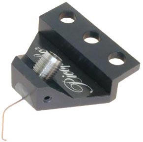


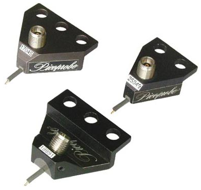
Durable RF probe Any pitch from 25 to 2540 microns DC to 40 GHz Insertion loss less than 0.8 db Return loss greater than 18 db Measurement repeatability better than -80db Individually spring loaded contacts BeCu , Tungsten or Nickel tips available Variety of footprints Patented coaxial design Available in thirteen styles Custom configurations available
|
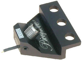
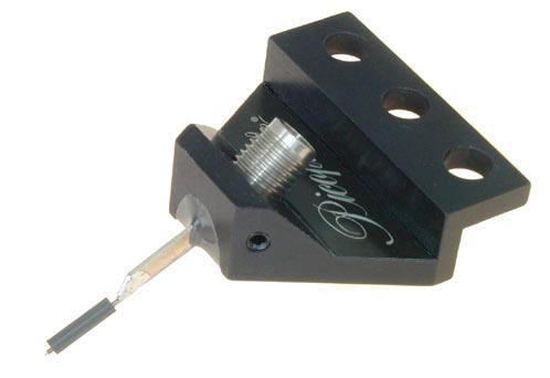
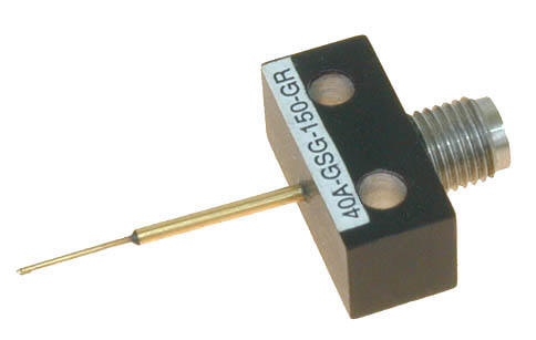
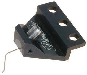
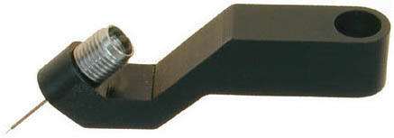
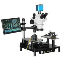
FIGURE 1
|
|
|
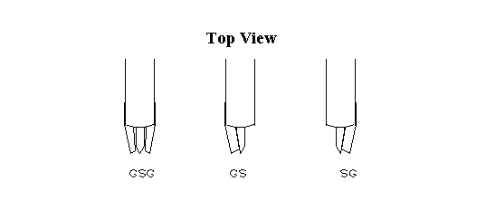
The GGB Industries, Inc., MODEL 40A microwave probe sets new standards in microwave probing performance. Using low loss coaxial techniques, the Model 40A achieves an insertion loss of less than 0.8 db and a return loss of greater than 18 db through 40 GHz. Any pitch (tip spacing) from 25 to 2540 microns may be specified. The probe can be configured with Ground-Signal-Ground (G,S,G), Ground-Signal (G,S), or Signal-Ground (S,G) tip footprints. Connection to the Model 40A is through a female K connector (2.9mm) which is 3.5mm connector compatible. |
|
|
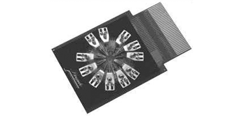
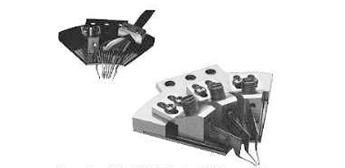
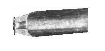
Flexible Tips for Flexible Probing Each Model 40A has patented, independently spring loaded tips which ensure a reliable contact to the probing surface. Because the tips are flexible they minimize circuit damage, increase probe life, and most importantly, provide a reliable individually spring loaded contact for each point. With a small amount of overdrive, the point scrubs the surface to make a reliable contact free of dust, dirt, and oxide contamination. A well-appreciated feature of the Model 40A is the ability to view the exact contact area which eases probe placement and allows for the precise positioning necessary for good LRM calibrations. The flexible tips even allow probing of non-planar surfaces such as ceramic substrates and laser diode structures.Coaxial Transmission Improves Performance The Model 40A uses a precision miniature 50 ohm coaxial cable from the probe tips to the connector interface. The coaxial design provides lower loss and less radiation than coplanar designs. The miniature coaxial cable is fabricated from flexible Beryllium-Copper which greatly improves the probe��s durability. It's sister probe, the Model 40M has the lowest insertion loss in the industry--less than 0.5db. Dual Microwave Probe The PICOPROBE® DUAL MICROWAVE PROBE consists of two separate probes mounted on a single holder. One probe is fixed to the holder; the other is adjustable. Each probe may be individually configured with GSG, GS, or SG footprints having any fixed pitch from 50 to 2540 microns. The probe to probe (signal to signal) spacing is user adjustable over a 4000 micron (160 mil) range. When ordering, an initial signal to signal spacing should be specified (up to .75 inches). Probe Cards Model 40A probes can be mounted on both industry standard 4.5 inch probe cards and custom-sized probe cards for testing wafers at high frequencies using standard automatic or manual probe stations. Picoprobe Probe Cards can be designed with all of our microwave probes operating from 40, 67, and 110 GHz for RF applications and can be combined with multiple DC needles for power and low frequency signals as well. Multi-Contact Wedges Our unique Multi-Contact Wedge designs accommodate multiple RF and DC contacts on a single, compact adapter. This compact design provides the user with a convenient method for testing wafers at high frequencies using standard automatic or manual probe stations. The user can choose from a variety of wiring options for the DC or power needles and select any combination of 40, 50, 67, and/or 110 GHz RF probes. |
|
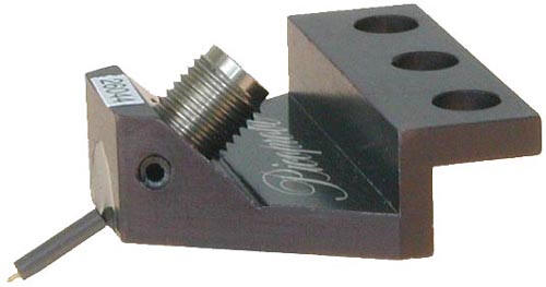
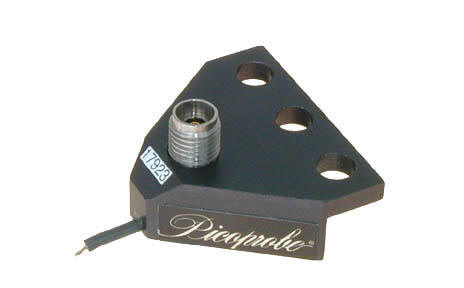
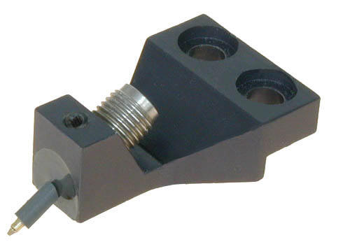
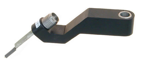
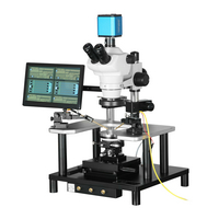
| FIGURE 2 |
An Entire Line of Microwave Probes
Other models of RF probes are available with standard tip spacings of up to 2540 microns. Larger tip spacings are available as well. For special applications, the Model 40A can be mounted in custom adaptors, the coaxial line can be bent to fit tight spaces, and the tips can be configured to match extremely non-planar surfaces or non-symmetrically placed grounds.
Other options include:
Tungsten or Nickel probe tips;
high temperature and high power versions;
custom "chip" probes which have integrated series, parallel or termination components built into the signal tip.
For applications above 40 GHz, GGB Industries, Inc., offers a complete line of microwave probes operating up to 1100 GHz (Model 1100). Several models are available with wave guide inputs: WR-22 for 33 to 50 GHz, WR-15 for 50 to 75 GHz, WR-12 for 60 to 90 GHz, WR-10 for 75 to 120 GHz, WR-8 for 90 to 140 GHz, WR-5 for 140 to 220 GHz, WR-3 for 220 to 325 GHz, WR-2.2 for 325 to 500 GHz, and WR-1 for 750 to 1100 GHz. The wave guide probes have an optional integral Bias T for active device measurements. Many other types and custom designs are available, so please call with your special application requirements.
Probing Expertise
With more than 25 years of probing experience, GGB Industries has broad capabilities in custom probe engineering and manufacturing. Our staff is accustomed to creating unique solutions for the most difficult probing requirements demanded by our customers. GGB Industries, Inc., is the leading supplier of high impedance active probes offering models with input capacitances of as low as .02 pF and frequency responses of up to 26.0 GHz.
Model 40A Performance Data |
|
|---|---|
| Frequency Range: | DC to 40 GHz |
| Insertion Loss: | Less than 1.0 db to 40 GHz (.70 db typical) |
| Return Loss: | Less than 30 db to 4 GHz (35 db typical) |
| Less than 20 db to 26 GHz (23 db typical) | |
| Less than 18 db to 40 GHz (20 db typical) | |
| Crosstalk: | Less than 38 db to 40 GHz |
|
Specifications are for the P-style Model 40A Picoprobes with G,S,G configurations and pitches between 50 and 300 microns.The C and T style Model 40A Picoprobes (see the following page for mounting styles)have the same specifications except for the insertion loss, which is less than 1.2 db (0.9 db typical) Crosstalk is measured using two probes contacting a bare sapphire substrate 100 microns apart. |
|
|
Model 40A Performance Data G,S and S,G Configuration |
|||
|---|---|---|---|
| Frequency Range: | DC to 40 GHz | ||
| Insertion Loss: | Less than 2.0 db to 40 GHz (1.6 db typical) | ||
| Return Loss: | Less than 30 db to 4 GHz | ||
| Less than 15 db to 26 GHz | |||
| Less than 12 db to 40 GHz | Specifications are for the P-style Model 40A Picoprobes | ||
| Data | |
|---|---|
|
|
| Crosstalk performance of two Model 40A-GSG-150-P Picoprobes while contacting a bare sapphire substrate with spacings of 100, 200, and 400 microns. | Typical uncalibrated performance of a Model 40A-GSG-150-P Picoprobe. The top trace is the round trip return loss into a short which is twice the probe's insertion loss. The bottom trace is the return loss into a 50 ohm load. |
|
|
| A Smith Chart showing the calibrated response of a Model 40A-GSG-150-P while contacting a coplanar offset short. The LRM method was used for calibration. | |
When ordering Picoprobe Model 40A probes, use the following part numbering convention:
ORDERING INFORMATION
When ordering Picoprobe Model 40A probes, use the following part numbering convention:
Model 40A-configuration �C pitch �C mounting style
MOUNTING STYLE:
Choose from thirteen adapter styles. Specify T, C, GR, P, DP, EDP, LP, Q, F, S, DS, VP, or RVP. Choose the appropriate mounting type for your application. The P, DP, EDP, LP, Q, S, DS, VP, and RVP styles have the connector pointing back at a 45 degree angle to give more working area above the probe. The DP, EDP, DS, VP, and RVP styles are used where extra clearance beneath the probe is needed. When using DP, EDP, and DS style probes, probe positioning is more difficult due to the increased probing angle since the probe points slide further forward for a given change in the Z axis than our other style probes. Custom mounting styles are available
EXAMPLE:
A 40A-GSG-150-P is a Model 40A with Ground, Signal, Ground configuration with 150 microns between each contact mounted in a P style adaptor.